Monday July 10, 2017 at 9:36am
Elite Applications Engineer Patrick Musgrave takes us through SWPCB Pattern Creation.
Component Wizard
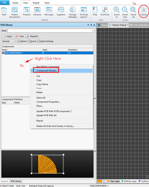
Most component patterns can be created from the component wizard, to access it:
1a. Enable the library panel
1b. Right click in the space shown below and choose 'Component Wizard'
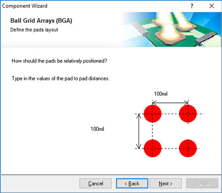
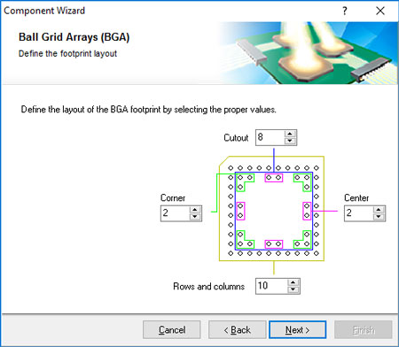
Component wizard allows you to create various arrays for different component types, simply step through the options and choose the settings as required.
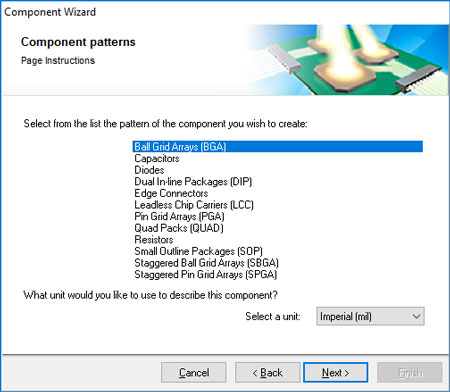
However, some complicated or unusual shapes cannot be created in this manner and require a different approach, below I will highlight methods of achieving linear and circular patterns.
Linear Patterns
As of now there are no pattern tools within SWPCB, and shapes must be created using a copy and paste approach. To do this in a linear fashion is quite straightforward:
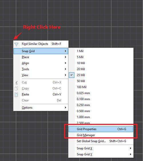
1. Set the grid to the desired spacing size using 'Grid Properties' or create a new, finer grid with 'Grid Manager'.
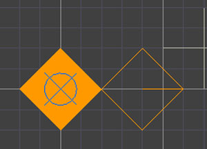
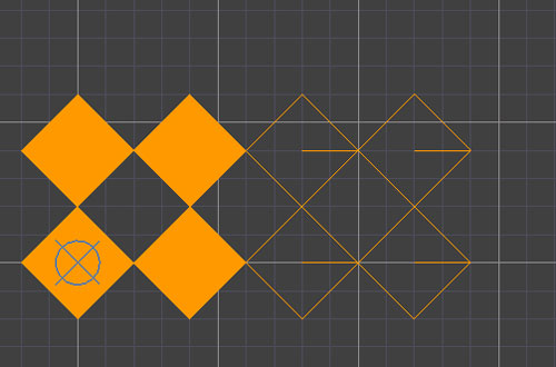
2. Copy (Ctrl + C, then select a reference point with a left click) and paste (Ctrl + V) the elements as required, you can copy multiple elements at once to speed things up.
Circular Patterns
Creating circular patterns is a little more complicated.
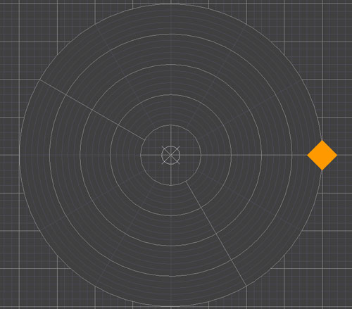
1. To begin create a Polar Grid, set the radial and angle step as required.
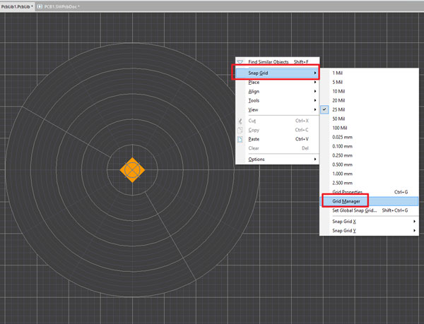
2. Then position the original shape into the correct start position.
3. Finish by copying, with the item's centre as the reference and pasting it directly onto the desired location.
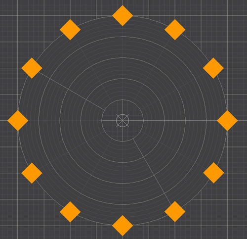
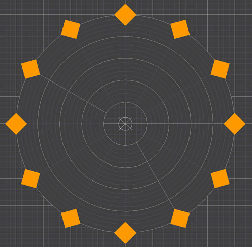
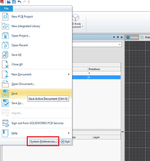
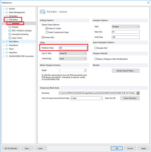
4. Alternatively copy the item choosing the centre point of the grid as the reference point. Then when pasting hit Space, this will rotate by a present amount that can be varied from Preferences -> PCB Editor -> General -> Rotation Step. These two methods will give slightly different results as shown.
Rotation step Location
Patrick Musgrave
Elite Applications Engineer