SOLIDWORKS Electrical Routing can automatically size wire and cable length. Occasionally, we may need to override the value that SOLIDWORKS reports.
Read on to learn how to override the reported values, how wire length is calculated in SOLIDWORKS Electrical Routing and what values influence the result.
SPLINE LENGTH VS ROUTE LENGTH
The main value taken into consideration is the Spline Length.
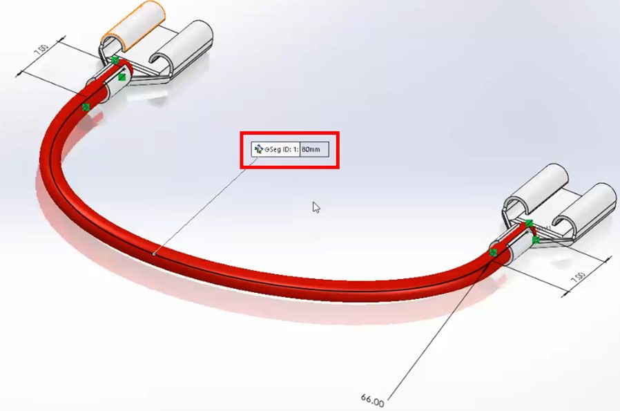
In the above picture, this value is 80 mm, but this might not be the only factor used to calculate the final length displayed in the BOM.
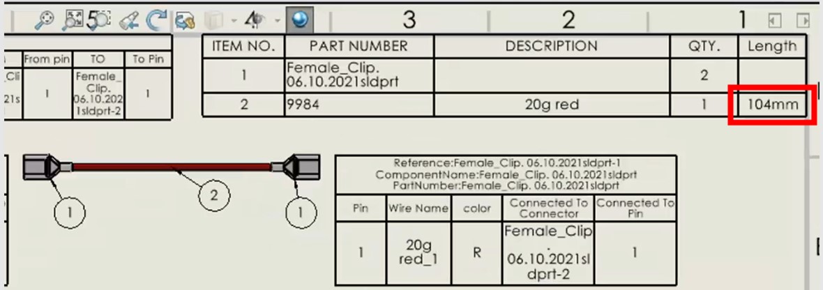
To demonstrate this, we can see in the associated BOM table below there is a discrepancy between the defined length of 80 mm and the final value of 104 mm.
While 80 mm may be the correct Spline Length, the BOM actually reports a different value: the Electrical Route Length.
This is calculated through the formula:
( Spline Length x Slack Percentage ) + Additional Internal Wire = Electrical Route Length
( 80 mm x 1.05 ) + 10 + 10 mm = Electrical Route Length
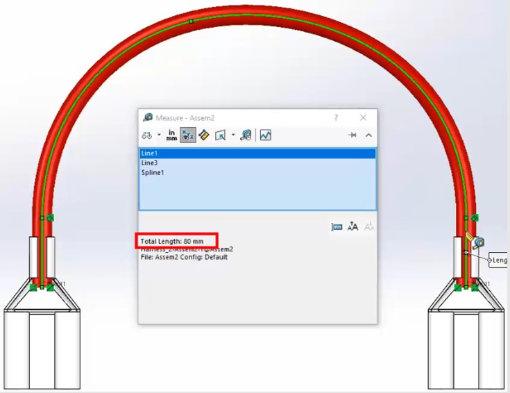
The Spline Length is the total length of the 3D sketch spline.
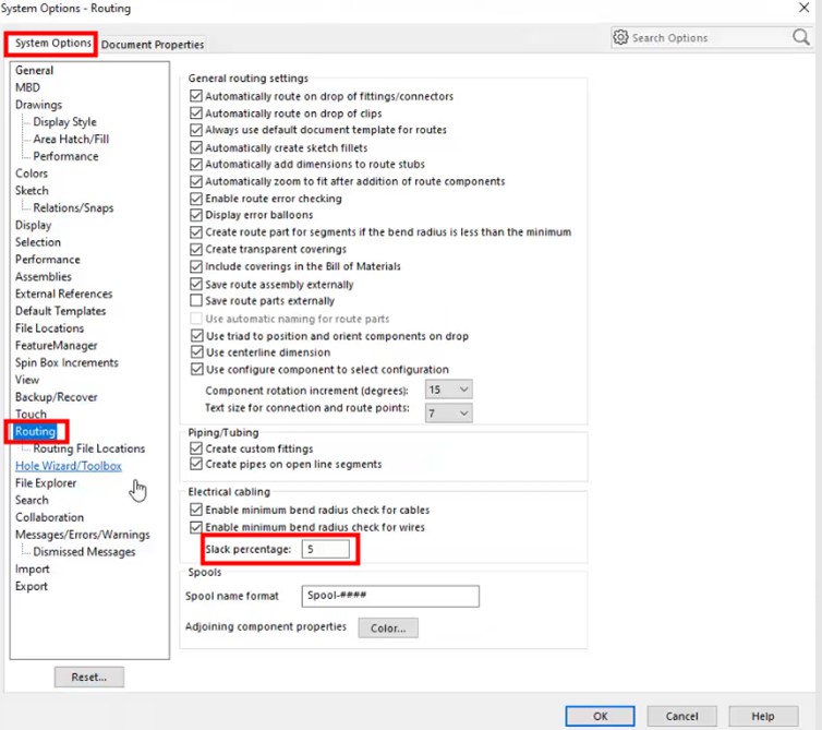
The Slack Percentage is a precautionary measure that allows for oversizing wire lengths. SOLIDWORKS increases the calculated cutting length of the wire to account for sagging, kinking and so on, which can occur in real life installations. This value is set to 0 by default.
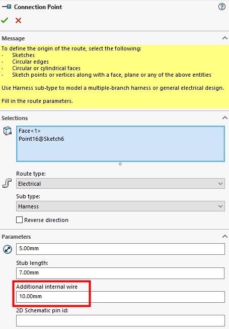
The Additional Internal Wire Length is a property that belongs to the Connection Point. It specifies a value to add to the cut length of the cable to allow the wire stripping.
WHY BOMS SHOW A DIFFERENT VALUE FOR LENGTH
Combining each of those parameters through the equation above gives us the Electrical Route Length, and explains why lengths may appear differently when measuring the length of wires and checking them against the length displayed in the BOM.
Our BOMs are helpfully accounting for real world scenarios, rather than the ideal world that exists within our SOLIDWORKS models.
Take the Next Steps...
Enhance your SOLIDWORKS Electrical skills with our CPD-accredited training courses.
Whether you’re a beginner or are intimately familiar with CAD, our friendly and expert trainers are ready to help you get the most out of SOLIDWORKS, either online or in a classroom local to you.