Marc has been able to model welding for more than 20 years.
It was developed as a result of customer requests as the potential savings from predicting welded structure behaviour virtually (over physical prototypes and manual iteration) were recognised.
MSC Marc can help to validate and inform decisions, for example, the use of a stitch welding scheme to minimise distortion.
We’ll be looking at the capability within the standard Marc solver, but there is a custom implementation, Simufact Welding, that is aimed at the manufacturing engineer rather than the FEA specialist.
So what do you need to add to a standard non-linear FEA capability in order to facilitate the simulation of welding?
There are a few key things:
- A moving heat flux to represent the heat input.
- The ability to introduce weld filler material as the flux progresses along the weld path.
- The ability to switch a contact model from ‘touching with separation’ to ‘glued’, triggered by a change in temperature to the melting point of the welded/weld materials.
Complex.
WELDING HEAT FLUX
There are two parts to approaching weld simulation.
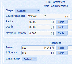
We need to define the dimensions of the weld pool (the volume into which heat is passed) and the path along which it passes.
The path can be defined by selecting a sequence of nodes or curves or by reference to a text file defining a sequence of XYZ locations.
The weld pool is defined by the dimensions of the pool as a cylinder, ellipsoid or cone along with the total power of the weld flux. As the pool passes along the path the heat is passed to those elements which fall within it resulting in their temperature increase.
WELD FILLER
The weld filler is a meshed region and can be 2D or 3D, as can be seen in the accompanying videos.
It is initially deactivated so there is no stiffness or load path contribution to the structure, but as the weld flux passes along, it is configured to activate those elements that have reached the defined melting point for the flux material.
A weld filler is not always necessary, as in the case of laser welding where we are simply fusing two parts together using heat from a laser.
CONTACT SWITCHING
We need the separate components of a weldment to be able to interact to capture the stiffness changes as the parts distort thermally.
We also need to be able to switch contact from a touching condition to a glued condition if the elements in contact see a temperature above melting.
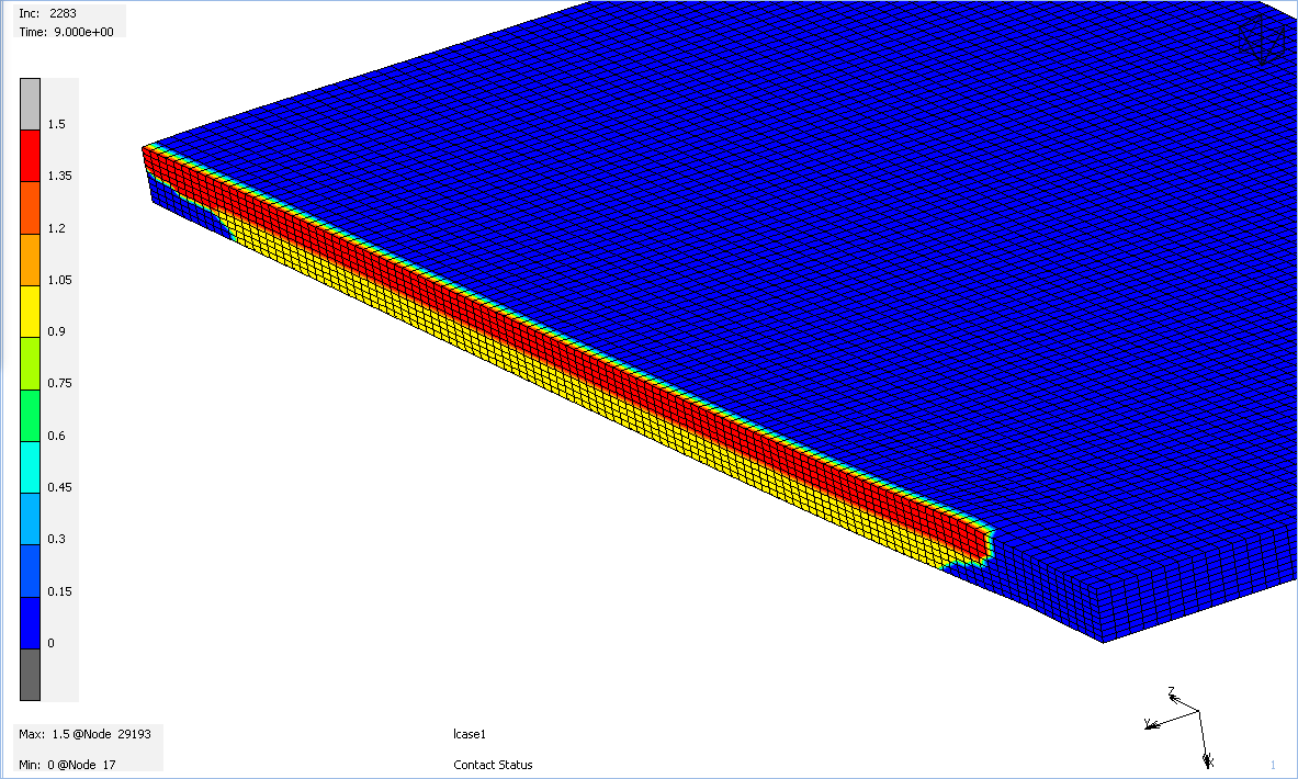
Marc has a result output called ‘contact status’. It’s a nodal scalar result of 0 for ‘not in contact’ 1 for ‘in touching contact’ and 1.5 for ‘in glued contact’.
We can see as the laser moves along the line between the two plates that there is touching contact ahead of it (in front of the magnified gapping caused by the heat distortion) and a value of 1.5 behind it as the two parts are fused together.
Looking at the contact pattern on just one half of the weld you can see the incomplete penetration where the red (glued) contact turns to yellow (touching) contact.
ENHANCEMENTS
As we have all the basic capabilities covered it’s worth touching on some other features of Marc that make this process all the more efficient.
The runtimes on these can be long so aside from the obvious use of parallel processing we have some specific ways to reduce the runtime.
MESH ADAPTIVITY
We can be looking at very large structures, one application for which this capability was developed was for welding truck ladder frames.
We have a weldment of several meters long but at we would like some finer detailed mesh around the area of the welding.
As the complete welding sequence will cover quite a lot of the structure we can make use of the adaptive meshing capability mentioned in a previous article to keep the overall model size down to speed up what can be a lengthy solution.
There are a couple of options open to us.
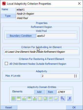
We can define criteria based on temperature, so that every element exceeding a trigger temperature is subdivided a number of times to improve the local result quality.
Or we can use the ‘node in weld pool’ method that follows the weld pool along, subdividing the elements within the pool and restoring them to the coarser representation as they pass from it.
PASS CONTROL
Thermal-structural coupling in Marc is a strongly coupled solution, meaning that each load/time increment involves the full solution and convergence of the thermal and structural domains as opposed to a weak coupling where thermal and structural domains are solved sequentially.
Strong coupling is more accurate but more computationally expensive.
The rapid high temperature changes in welding mean that the time stepping is driven by the thermal solution carrying additional possibly unnecessary structural iterations along with it increasing the runtime.
The simple change made is to change the frequency of the structural solution, called pass control.
This allows us to run specify, for example, that a combined structural thermal solution is only performed for every five thermal steps.
The thermal steps on their own are quicker and, providing we don’t skip too many, the strong coupled increment every fifth step keeps the solution stable.
This was developed as a result of extensive work in the Simufact product and can have a dramatic effect on solution time with no adverse effect on the quality of predictions made by the software.
CONCLUSION
Welding simulation has been used on structures as large as trucks and as small as heart pacemakers to successfully develop welding schemes to get the best quality products.
MSC Marc is available within the MSC One product set, meaning that it can be remarkably affordable to use for smaller companies through the Start Edition version.
If you want to learn more, or have other manufacturing tasks you would like to simulate such as pierceing, riveting, induction welding, forging. forming etc please get in touch for a conversation with our technical team.